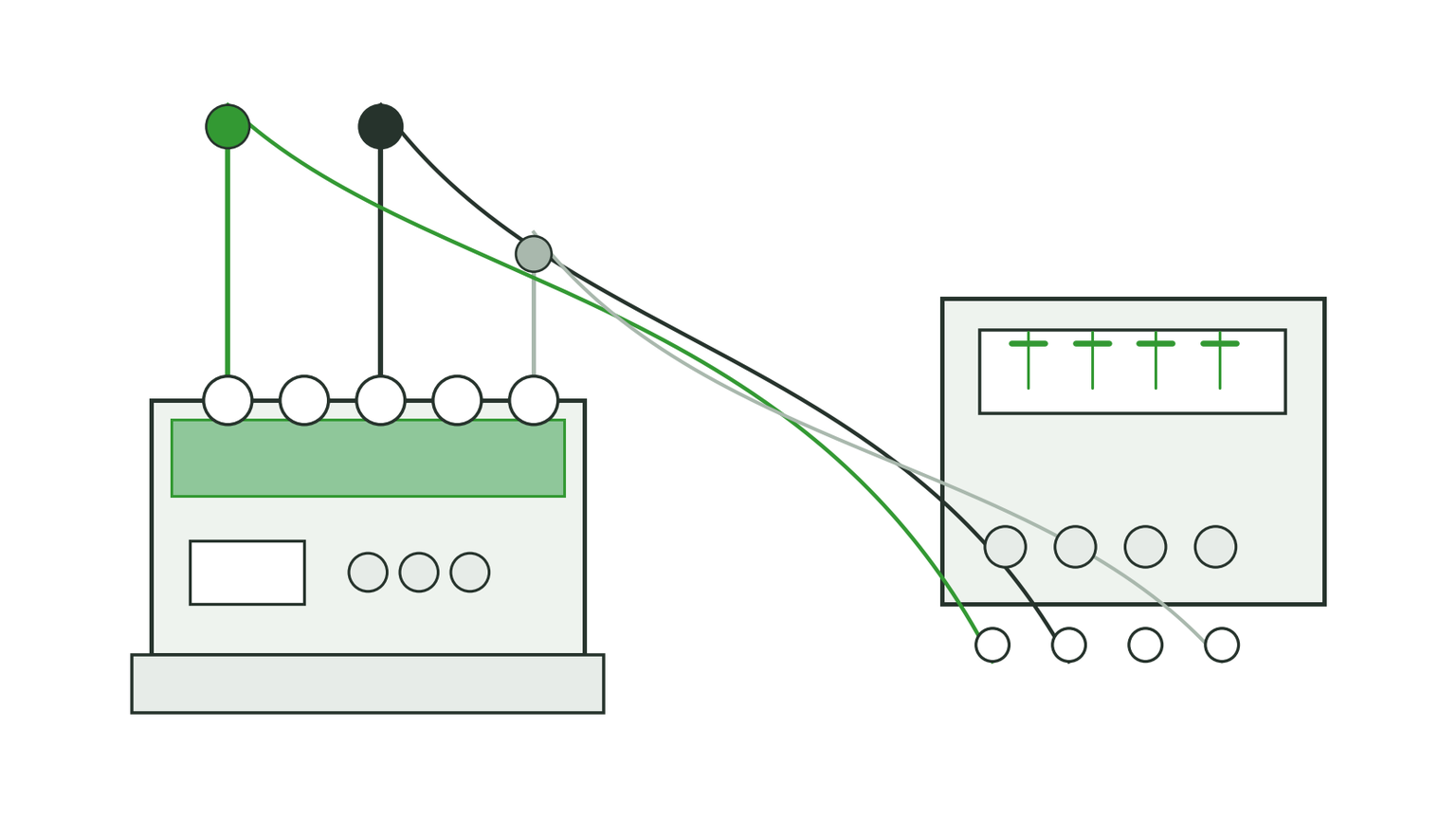
Pyrometry & Thermocouples
Thermocouple type
| Type | Calibration | Range | Features |
|---|---|---|---|
| K type ( Ni-Cr – nickel-silicon) | NiCr-NiAl | −200–1260°C | Most common, low cost, oxidation resistance is moderate, long-term drift |
| N type | Nicrosil-Nisil | −200–1300°C | Ratio K type oxidation-resistant, better stability, high-temperature furnace trend |
| R/S type ( platinum-rhodium) | PtRh-Pt | 0–1600°C | Noble metal, high accuracy, used for instrument and TUS |
| B type ( platinum-rhodium 30- platinum-rhodium 6) | Pt30Rh-Pt6Rh | 0–1800°C | High temperature, no thermoelectric EMF at ambient |
Compensating cable
Must match the thermocouple calibration (K type uses green +/−, extension-wire type KX); polarity must not be reversed; single-point ground to avoid ground loops; in high-temperature zones use heat-resistant extension wire or extend the thermocouple itself.
Thermocouple installation checklist
- Insertion depth ≥ protection-tube inner diameter 8–10 times, place the hot junction at a representative part location;
- Avoid contact with the furnace wall / heating element, ceramic tube free of cracks;
- Terminal screws tight, extension-wire polarity correct;
- Note the grounding method for mineral-insulated thermocouples ( insulation / grounded) match the controller;
- Record number, location, insert date and reading.
SAT system-accuracy test (AMS 2750)
- Use a standard thermocouple (R/S type) compare at the same location as the instrument thermocouple;
- Take multiple points above and below the working temperature ( such as 3 point) measurement;
- System error = instrument reading − standard value, should be within tolerance (Class 2:±3°C or 0.3%);
- On out-of-tolerance, check the extension wire, terminal, cold-junction compensation and instrument calibration.
TUS furnace-temperature uniformity test
- Loaded thermocouple ≥ 9 pcs (Class 2 furnace), arrange to cover the work zone;
- Empty furnace / full load must all be tested, perform per the calibration cycle ( usually 6–12 months);
- Acceptance band ±6°C(Class 2), if exceeded, adjust combustion / power zoning or shorten the soaking window;
- Archive the test data, bound to the heat-treat record.
Instrumentation & Measurement
1. Calibration basis and standards
Calibration= compare instrument readings with known reference standards, then adjust or record the error.
- Accuracy:Ensure correct measurement ( quality, safety, key to legal compliance)
- Traceability:Measurement results traceable to the national standard ( UK NPL, US NIST)
- Regulatory requirement:ISO 9001,AMS 2750( heat treatment),FDA( pharmaceutical) all require instruments under controlled calibration
1.1 calibration interval
| Instrument type | Typical interval | Cases for shortening the interval |
|---|---|---|
| Process thermocouple | 6-12 months | Harsh environment (>1000°C), frequent thermal cycling |
| RTD(PT100) | 12 months | Vibration, corrosive atmosphere;AMS 2750 requirement 6 months |
| Pressure transmitter | 12-24 months | Overpressure event, fouling / corrosive medium |
| Flowmeter | 12-36 months | Abrasive fluid, custody transfer ( shortened to 6-12 months) |
1.2 external calibration (UKAS/ISO 17025) compared with internal calibration
| Method | Executor | Cost ( UK reference) | Applicable occasions |
|---|---|---|---|
| External calibration by an accredited laboratory | ISO 17025 accredited laboratory ( traceable to the national standard) | £80-300 / pcs | Legal metrology,AMS 2750,FDA/ pharmaceutical, customer requirement |
| Internal calibration | A competent technician uses accredited-calibrated reference standards | £10-50( manual only) | Internal QC,ISO 9001( when the procedure is documented) |
Key rules:The reference standard itself must be calibrated by an accredited body; process instruments can be calibrated internally using these reference standards.
2. Temperature-instrument calibration
2.1 equipment requirement
| Equipment | Typical specification | Cost ( UK reference) |
|---|---|---|
| Dry-well calibrator | Range 50-660°C, stability ±0.1°C, accuracy ±0.25°C | £1,500-5,000 |
| Reference thermocouple | K type 1 class or SLE, accredited calibration | £150-400 |
| Precision thermometer | Resolution 0.01°C, accredited calibration | £500-2,000 |
2.2 thermocouple calibration procedure
- Installation:Insert the reference and unit-under-test thermocouples together into the dry-well holes ( improve contact with thermal grease)
- Set:Start from the lowest calibration point ( such as 200°C)
- Stable:Wait 10-15 min (±0.5°C maintain 5 min)
- Record:Reference = 200.2°C, unit under test = 199.5°C → error = −0.7°C
- Multi-point:Take 3-5 points ( such as 200/400/600/800/1000°C)
- Documented:All readings and errors recorded in the calibration certificate
- Adjust:When error exceeds tolerance, adjust the controller offset or apply a correction
2.3 thermocouple tolerance (IEC 60584)
| Model | 1 class tolerance | 2 class tolerance | Range |
|---|---|---|---|
| K type | ±1.5°C or ±0.004×T | ±2.5°C or ±0.0075×T | −40 ~ +1200°C |
| N type | ±1.5°C or ±0.004×T | ±2.5°C or ±0.0075×T | −40 ~ +1300°C |
| R type | ±1.0°C or ±[1+0.003×(T−1100)] | ±1.5°C or ±0.0025×T | 0 ~ +1600°C |
2.4 PT100 resistance – temperature comparison
| Temperature | Resistance (Ω) | A class tolerance |
|---|---|---|
| −50°C | 80.31 | ±0.24°C |
| 0°C | 100.00 | ±0.15°C |
| 100°C | 138.51 | ±0.35°C |
| 200°C | 175.86 | ±0.55°C |
| 400°C | 247.09 | ±0.95°C |
3. Pressure-instrument calibration
3.1 equipment
| Equipment | Range | Accuracy | Cost ( UK reference) |
|---|---|---|---|
| Piston gauge (deadweight tester) | 0-700 bar | ±0.015%( optimal) | £3,000-15,000 |
| Digital pressure calibrator | 0-400 bar | ±0.025-0.05% FS | £2,000-8,000 |
| Hand pump + standard gauge | 0-40 bar | ±0.1% FS | £500-2,000 |
3.2 calibration procedure
- Connection:Hand pump → reference gauge → transmitter under test ( in series, via the valve manifold)
- Zero point:Vented to atmosphere (0 bar) should read 4.00mA
- Pressurize:Of the range 25% / 50% / 75% / 100%
- Record:At each point record the reference-gauge reading and transmitter output
- Reduce pressure:Reduce pressure in the reverse direction to check hysteresis
- Calculate:The maximum error should < ±0.5% FS
- Adjust:Zero point / range screw or HART communicator
3.3 4-20mA signal calculation
Example:0-10 bar transmitter, actual pressure 7.5 bar → range 75% → expected 16.00mA; if measured 16.3mA → error +0.3mA = +1.875% FS( out of tolerance).
3.4 pressure-gauge accuracy class (BS EN 837-1)
| Class | Accuracy (% FS) | Typical use |
|---|---|---|
| 0.1 class | ±0.1% | Reference standard |
| 0.25 class | ±0.25% | Verification gauge |
| 1.0 class | ±1.0% | Process gauge ( industrial standard) |
| 1.6 class | ±1.6% | General indication |
4. Flowmeter calibration
4.1 calibration methods for each flowmeter type
| Type | Method | Accuracy | Cost ( UK reference) |
|---|---|---|---|
| Electromagnetic flowmeter | Dry type ( electronic) or wet type ( weighing) | ±0.2-0.5% | £80-2,000 |
| Coriolis mass flowmeter | Electronic verification or wet type | ±0.1-0.2% | £150-5,000 |
| Turbine flowmeter | Wet calibration only | ±0.5-1.0% | £500-3,000 |
| Orifice plate / differential pressure | Measure the orifice diameter + calibrate the differential-pressure transmitter | ±1-3% | £150-500 |
4.2 calibration by weighing method ( gold standard for liquid flow)
- Switch the flow to the collection vessel on the weigh platform
- Start the timer and record the initial weight
- Collect a known time interval ( such as 60 s)
- Stop and record the final weight
- Calculate: flow =( weight / density)/ time
- Compared with the flowmeter reading, adjust K coefficient
4.3 orifice-plate inspection
- Orifice diameter: caliper measurement (±0.01mm), compared with the nameplate
- Inlet edge: must be sharp ( free of burrs, roundness <0.0005d)
- Flatness: check flatness with a straightedge
- Pressure tap: clean and unobstructed, correct spacing (D and D/2 or flange tapping)
- Replacement condition: orifice diameter deviates from nominal >±0.5%, edge damage, visible corrosion
5. Level-instrument calibration
5.1 type and method
| Type | Principle | Method | Accuracy |
|---|---|---|---|
| Differential-pressure type | Static pressure P = ρgh | Calibrate the differential-pressure transmitter 0-100% | ±0.5-1% FS |
| Ultrasonic | Acoustic path time in air | Compared with tape-measure field measurement | ±1-3% FS |
| Radar ( guided-wave) | Microwave time-of-flight | Dry or wet calibration | ±1-5 mm |
| Capacitive type | Permittivity change | Analog or wet calibration | ±1-2% FS |
5.2 differential-pressure level transmitter
Example:Water tank 0-5m, water density 1000 kg/m³ → 5m pressure at = 1000 × 9.81 × 5 = 49,050 Pa = 0.49 bar → transmitter range 0-0.49 bar corresponding 4-20mA.
5.3 calibration steps
- Isolation:Close HP/LP valve, open the equalizing valve
- Connection:Hand pump + reference gauge connected to HP side,LP vented to atmosphere
- 0% calibration:Add 0 mbar should read 4.00mA
- 100% calibration:Add ρgh the corresponding pressure should read 20.00mA
- Linearity:Test 25/50/75%( increase pressure + reduce pressure)
- Adjust:Zero point / range button or HART
- Restore:Close the equalizing valve, open the isolation valve, leak detection
6. Calibration procedure and records
6.1 required record elements
- Instrument identification: tag number, serial number, brand / model
- Date + technician name
- Reference standard: brand / model / serial number + its validity period ( must be within the calibration validity period)
- Environment: temperature ±2°C, humidity, atmospheric pressure
- As-Found data:Pre-adjustment reading
- As-Left data:Post-adjustment reading
- Pass / fail criterion ( based on the tolerance)
- Next calibration date = calibration date + interval
- Affix labels: green ” calibration due:MM/YYYY”
6.2 determine tolerance by application
| Application | Typical tolerance | Reason |
|---|---|---|
| General indication | ±1-2% FS | Non-critical, monitoring only |
| Control loop (PID) | ±0.5-1% FS | Affects product quality |
| Safety interlock | ±0.25-0.5% FS | Failure implies a safety risk |
| AMS 2750 temperature measurement | ±3°C or ±0.5% | Statutory requirement ( aerospace) |
| Custody transfer | ±0.1-0.25% | Involving financial settlement |
6.3 label-color management
| Color | Status | Action |
|---|---|---|
| Green | Calibration valid | Normal use |
| Amber | Approaching expiry (30 day(s)) | Schedule calibration, may continue to be used |
| Red | Overdue for calibration / fail | Prohibited— re-calibrate |
7. Measurement uncertainty and TUR
7.1 test uncertainty ratio (TUR) (TUR)
Criteria:TUR ≥ 4:1( preferred), minimum 3:1(ISO 17025).
Example:Process-transmitter tolerance ±0.5% FS = ±0.05 bar(0-10bar); reference-gauge uncertainty ±0.015 bar → TUR = 3.3:1 → acceptable.
7.2 uncertainty source
| Source | Contribution | Reduction measures |
|---|---|---|
| Reference-standard accuracy | 50-70% | Use a better reference ( piston type vs digital) |
| Resolution | 10-20% | Improve resolution (0.01°C vs 0.1°C) |
| Temperature effect | 5-15% | Controlled environment (20°C ±2°C) |
| Repeatability | 5-10% | Multiple readings (3-5 times) take the average |
7.3 combined uncertainty
Root-sum-square:U = √(U₁² + U₂² + U₃² + …)
8. Temperature controller and instrument configuration
Common furnace temperature-control instruments include single-loop PID controller ( such as Eurotherm 3216/3504 series), multi-loop program controller ( heat-treatment process curve), recorder and over-temperature protector. Configuration key points:
- Input type must match the sensor (K/N/R/S/B/PT100), cold-junction compensation enabled
- Output type selected by load ( relay /SSR drive /4-20mA/ thyristor (SCR))
- Over-temperature protection must useIndependent instrument, do not use PID controller software alarm substitution
- The calibration interval for the controller and safety instruments is per AMS 2750 or executed under an internal quality system
- Communication (Modbus RTU/RS-485) used for data acquisition and audit trail
See the terminal and output configuration for detailsWiring reference; see furnace temperature uniformity testing.
9. Oxygen probe ( carbon-potential sensor)
The oxygen probe measures the atmosphere oxygen potential via a zirconia element, convert to carbon potential (CO/CO₂ balance). Maintenance key points:
- Reference gas ( clean air) stable flow, unobstructed piping
- Install the probe away from direct impingement of the carburizing-agent nozzle, sense a representative atmosphere
- Periodic carbon burn-off cleaning (soot cleaning) checked against impedance
- Use standard gas per the manufacturer interval ( such as 1% O₂) verify the millivolt output
- Probe at end of life ( usually 12-24 months) then output attenuation, replace promptly
See carbon-potential calculation.
10. Vacuum gauge
| Type | Range | Depends on gas type | Description |
|---|---|---|---|
| Bourdon tube / diaphragm | Ambient air ~ approx. 1 mbar | No | Mechanical direct measurement |
| Thermocouple vacuum gauge | Ambient air ~ 10⁻³ mbar | Is | Resistance vacuum gauge, low cost |
| Pirani gauge | Ambient air ~ 10⁻⁴ mbar | Is | Heat-conduction type |
| Capacitance diaphragm gauge (CDG) | Ambient air ~ 10⁻⁵ mbar | No | Independent of gas type, high accuracy |
| Ion gauge ( Penning / cold cathode) | 10⁻³ ~ 10⁻⁹ mbar | Is | High-vacuum measurement |
Calibration: thermocouple / the ion gauge can be compared with a capacitance diaphragm gauge; gauge-tube contamination ( oil vapor, dust) causes reading drift, clean or replace periodically.
11. CQI-9 heat-treatment system assessment
CQI-9(AIAG special process: heat-treatment system assessment) is a mandatory requirement of the automotive supply chain, core concern:
- High-temperature test (Pyrometry):TUS/SAT execute, instrument calibration, record retention ( according to AMS 2750 or equivalent)
- Process:Process specification, process monitoring ( temperature / carbon potential / time), mistake-proofing
- Equipment capability:Furnace temperature uniformity, quench system, atmosphere control
- Personnel and records:Training matrix, audit trail, nonconforming-product control
12. AMS 2750 high-temperature measurement
AMS 2750″ high-temperature measurement ” is the baseline standard for aerospace heat treatment, requirements for furnace instruments:
| Item | Requirement |
|---|---|
| Furnace temperature class | Classify per process requirements (Class 1-6), uniformity ±3°C ~ ±15°C not equal |
| Instrument calibration | Thermocouple and RTD calibration interval 6 months; reference standard traceable |
| TUS | Before first use + routine interval ( typically every 6 months)+ after major overhaul |
| SAT | Quarterly ( maximum 3 months)+ before commissioning after repair |
| Record retention | Calibration certificate,TUS/SAT report, over-temperature record retention period per contract / specification |
Related tools:·
Comments
No comments yet. Feel free to ask your model-selection or technical questions; we will reply after review.
Comments are closed on this page.